Background and Methods Section - Informal Comparison of the Relative Brightness of an Astronomy Green Laser Pointer . . .
Rev. November 1, 2005
3.1.1 Biological Effects of Class IIIA Laser Pointers
Users of Class IIIA green laser pointers should understand that the FDA regulations,37 setting standards for the manufacture and sale of these devices were never intended to offer a no-injury level of protection. An assumption inherent in the regulations is that "depending upon the irradiance, [they are] either an acute intrabeam viewing hazard or chronic viewing hazard, and an acute viewing hazard if viewed directly with optical instruments."37 The FDA intended to rely on a person's averted vision or blink reflex to make them turn away from a Class IIIA low-power consumer laser pointer beam before eye injury would occur.
Three reports in medical journals discuss the worst-case scenarios of involving persons looking directly into red and green Class IIIA lasers at close range and for an extended duration. A fourth concerns a less powerful Class II laser pointer.
Considering the FDA's assumption, it was encouraging when in Robertson et al. (2000).31, three persons scheduled to have their retinas removed due to cancer volunteered to stare directly into a red Class IIIA laser for an extended period, and no changes to retinal tissue were seen. They reported no vision effects other than short-term after-images. After cancer surgery, their retinas were biopsied. Examination of the retinas with an electron microscope showed no abnormalities at the sites exposed to the red Class IIIA laser beam.
Conversely, in a second report44 a physician found phototoxic damage and vision loss in a eleven year-old girl who had stared, on a "dare" from a classmate, into a red Class IIIA laser for several "multi-second" exposures. She suffered an immediate and permanent decrease in visual acuity. Examination "disclosed pigmentary clumping in the central fovea with loss of the central foveal reflex." Zamir (1998)45 ancedotally reported permanent persistent retinopathy and some decrease in the brightness of images in a 19 year-old woman who intentionally stared into a Class II laser pointer for 10 seconds.
In the third May 2005 report, discussed above, Robertson et al. (2005)32 repeated their 2000 red laser experiment with a consumer green laser pointer and exposed a volunteer cancer patient's eyes to 60 seconds, 5 minutes and 15 minutes of green laser pointer light. Robertson found that green laser pointers produced pathological changes in the in retinal pigment epithelium in the area exposed for only 60 seconds. Signs seen were consistent with eye injuries from industrial laser accidents.33 Robertson (2005) also reported he was unable to detect any vision defect in his patient, although the photographs in Robertson's article show a clearly disfigured retina.
An individual's phototoxic response to either intense coherent laser light or incoherent light depends on exposure to light-sensitizing chemicals contained in dietary supplements, cosmetics, or drugs.33,34,35 Combination effects of consumer laser pointers and other drugs have not been systematically studied by industry or medical researchers.
3.1.2 Visual Effects of Class IIIA Laser Pointers
In the 1990s, the Federal Aviation Administration (FAA), in response to complaints from commercial airline pilots about strikes from high-intensity lasers used at outdoor light shows in Las Vegas, conducted a study of the visual effects of lasers, including lower-power Class IIIA lasers. That study defined various "hazard zones" within which certain visual effects would be seen:
Table 3 - Nominal Hazard Zones (NHZ) for Visible Diode Pointers
Power: 5 mW | Divergence: 1 milliradian | Beam size: 2 mm
| Bioeffect
|
MPE Level* (W/cm^2) |
Nominal Hazard Zone (feet) |
| Blink reflex |
2.6 x 10⁻³ |
51 |
| Flash-blindness/afterimage
|
100 x 10-6 |
262 |
| Glare |
5 x 10⁻⁶ |
1,171 |
| "No effect" |
50 x 10-9 |
11,707 |
* MPE = Maximum permissible exposure
The different visual effect "MPE" criteria used in the NHZ computations in [the above table] . . . are based upon the U.S. Standard for the Federal Aviation Administration: FAA 74002D Outdoor Laser/High Intensity Light Demonstrations which provide a numerical basis for the various bioeffect criteria.
Excerpt from Rockwell "Safety Recommendations of Laser Pointers"2 quoting FAA 74002D Outdoor Laser/High Intensity Light Demonstrations: From Chapter 34: Outdoor Laser/ High Intensity Light Demonstrations, Federal Aviation Administration << http://www.rli.com/resources/pointer.asp undated, accessed 1/5/2005 >>.
These biological effects at distance were incorporated in subsequent ANSI standards for the safe user of lasers.27
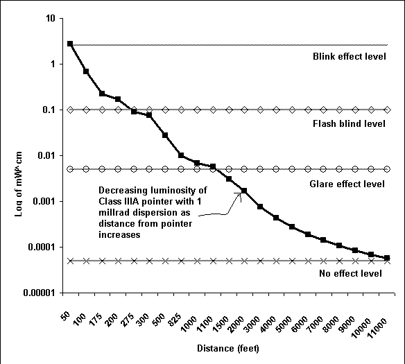
Assuming a 1 milliradian dispersion of the pointer's laser beam - as the FAA did - the following graph and table predicts beam size and intensity at various distances. The graph also relates the predicted intensity of a 5 milliWatt green laser pointer with a 1 milliradian dispersion to the FAA nominal hazard zones. The predicted intensities comport well with the intensities reported at those same distances in the FAA study:

Figure 15 - Predicated 1 milliradian dispersion of green laser pointer with FAA nominal hazard zones
In this figure, the pointer's luminosity is graphed as the heavy-black line with square markers. The pointer's luminosity is scaled logarithmically on the y-axis. The luminosity graph of a Class IIIA laser with an initial power of 5 milliWatts begins at about 2.7 milliWatts per square centimeter at a distance of 50ft (15 meters) and proceeds across the graph from the left to right in increasing distance and descending intensity. 50ft (15 meters) is the end of the FAA "blink" or averted response zone. The horizontal markers represent the laser intensity at which the FAA reported biological effects in Table 2. The FAA "blink" or averted response zone ends at about 0.1 milliWatts per square centimeter, or about one-tenth that initial luminosity. The FAA flash-blindness zone ends at about one-hundredth of initial luminosity, the glare zone at one-thousandths, and the no-effect zone at one-ten-thousandths. This graph summarizes the following tabular data:
Table 4 Predicted brightness/distance for Class IIIA lasers 5mW< initial power and 1 milliradian dispersion
| Dt ft |
Dt m |
Bdiain |
Bdiacm |
BAreain |
BAreacm |
W^cm | Per | dlt_mag |
| 50 |
15 |
0.6 |
2 |
0.3 |
1.8 |
2.74E-03 | 54.82% | 8.2 |
| 100 |
30 |
1.2 |
3 |
1.1 |
7.3 |
6.85E-04 | 13.70% | 9.7 |
| 175 |
53 |
2.1 |
5 |
3.5 |
22.3 |
2.24E-04 | 4.475% | 10.9 |
| 200 |
61 |
2.4 |
6 |
4.5 |
29.2 |
1.71E-04 | 3.426% | 11.2 |
| 275 |
84 |
3.3 |
8 |
8.6 |
55.2 |
9.06E-05 | 1.812% | 11.9 |
| 300 |
91 |
3.6 |
9 |
10.2 |
65.7 |
7.61E-05 | 1.523% | 12.0 |
| 500 |
152 |
6 |
15 |
28.3 |
182.4 |
2.74E-05 | 0.548% | 13.2 |
| 825 |
251 |
9.9 |
25 |
77.0 |
496.6 |
1.01E-05 | 0.201% | 14.2 |
| 1000 |
305 |
12 |
30 |
113.1 |
729.7 |
6.85E-06 | 0.137% | 14.7 |
| 1100 |
335 |
13.2 |
34 |
136.8 |
882.9 |
5.66E-06 | 0.113% | 14.9 |
| 1500 |
457 |
18 |
46 |
254.5 |
1641.7 |
3.05E-06 | 0.061% | 15.5 |
| 2000 |
610 |
24 |
61 |
452.4 |
2918.6 |
1.71E-06 | 0.034% | 16.2 |
| 3000 |
914 |
36 |
91 |
1017.9 |
6566.9 |
7.61E-07 | 0.015% | 17.0 |
| 4000 |
1219 |
48 |
122 |
1809.6 |
11674.5 |
4.28E-07 | 0.009% | 17.7 |
| 5000 |
1524 |
60 |
152 |
2827.4 |
18241.5 |
2.74E-07 | 0.005% | 18.2 |
| 6000 |
1829 |
72 |
183 |
4071.5 |
26267.7 |
1.90E-07 | 0.004% | 18.5 |
| 7000 |
2134 |
84 |
213 |
5541.8 |
35753.3 |
1.40E-07 | 0.003% | 18.9 |
| 8000 |
2438 |
96 |
244 |
7238.2 |
46698.2 |
1.07E-07 | 0.002% | 19.2 |
| 9000 |
2743 |
108 |
274 |
9160.9 |
59102.4 |
8.46E-08 | 0.002% | 19.4 |
| 10000 |
3048 |
120 |
305 |
11309.7 |
72965.9 |
6.85E-08 | 0.001% | 19.7 |
| 11000 |
3353 |
132 |
335 |
13684.8 |
88288.7 |
5.66E-08 | 0.001% | 19.9 |
Dt ft = Distance feet
Dt m = Distance meters
Bdiain = Beam diameter inches at distance
Bidacm = Beam diameter centimeters at distance
BAreain = Beam area inches at distance
BAreacm = Beam area centimeters at distance
mW^cm = milliWatts per square centimeter
Per = change in milliWatts per square centimeter from distance zero (5mW) to distance
dl_mag = same as Percent, expressed in changes in magnitude
delta_mag (m1 - m2) = 2.5 * log_10 * ( mW^cm / 5mW at zero distance )
Delta_mag is not the apparent magnitude, since magnitude at distance zero is not known.
One amateur astronomer concern what harm might be caused to vision by an accidental beam strike down a telescope tube and up the eyepiece during co-observing at star parties.
With respect to this issue, some basic telescope optical principles concerning point sources and extended sources should be recalled. Telescopes can intensify point sources - this is the light grasp of the telescope. However, magnified extended objects are always dimmer than their brightness seen with the naked-eye. The relative brightness of a magnified object is expressed in the relationship -
( Diameter_objective2 ) / (D_eye_pupil)2 * Magnification2
A green presentation pointer is an extended object at close distances - they have an approximately 1 to 2 millimeter aperture. As shown in Table 3 due to their 1 milliradian dispersion, the Class IIIA laser's beam also is an extended object at distances over 50ft.
Because of this optical principle, even if a Class IIIA green laser beam does accidentally strike down a telescope and up the eyepiece into an observer's eye, the magnified image will not have a more concentrated power (in terms of W/cm^2) than the original beam exiting the laser. Figures 10 through 12 illustrate how a pointer's beam is dispersed by magnification when a Class IIIA green pointer, held about 6 inches (15 1/4 cm) from the objective of a small refractor, is aimed down the optical axis:
In conclusion, the risk to vision by an accidental strike down a telescope tube is not greater than having the laser beam directly enter your pupil from a short distance. In theory, your averted vision or blink reflex would force you to involuntarily turn away from the eyepiece before any vision damage could occur.
This situation regarding Class IIIA laser beams should be distinguished from the harm that Class IIIB lasers or more powerful military lasers could cause. Because Class IIIB lasers have sufficient power to severely injure your eye before your averted vision response forces you to turn away, it is possible for a telescope or binoculars to collimate sufficient power from the beam that would injure an observer's eye before the observer's blink reflex forced them to turn away. Military battlefield targeting lasers are an extreme example of this principle. Military battlefield targeting lasers are so powerful, that the safe naked-eye viewing distance is 6 to 10 miles (approx. 9.5 to 16 kilometers) and with binoculars 40 to 50 miles (approx. 64 to 84 kilometers) off-center of the beam's optical axis.46 Any telescopic collimation of such a beam would be immediately injurious, but Class IIIA lasers are not that powerful.
However, it bears repeating that government regulations,37 and publications42,43, product literature41 and industry literature5,24 warn against ever viewing a Class IIIA laser beam with binoculars or telescopes. I certainly would not test the proposition by staring down the eyepieces of any refractor, like that shown in Figures 10 through 12, nor should anyone reading this article attempt to do so.
Astronomical 20x70mm binoculars were mounted on a parallelogram binocular mount equipped with a fine focusing adjuster and a red-dot pointer. A Leading Light Technology, Inc.41 Class IIIA green laser pointer was strapped and aligned with the binoculars. The presentation pointer was purchased from a local planetarium and is marketed for astronomy use. The pointer bears the "Danger" label required by 24 C.F.R. 1040.10 (2000)37 for Class IIIA lasers emitting between 2.5 and 5 milliWatts of power. The binocular-pointer setup is illustrated in the following figures:
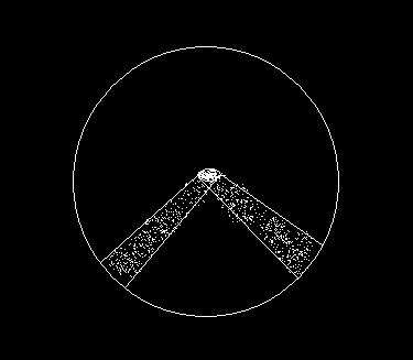
The third illustration to the right shows an unexpected optical illusion seen through the binoculars. Although only one laser beam is used, when the eye merges the two binocular views into one image, two beams are seen. The illusory beams converge from the left and right and merge into a single, brighter terminal disk. This visual illusion is not seen when binoculars are held in one hand and the laser pointer is held at an arm's length off to one side.
The mounted 20x70mm binocular was supplemented with a hand-held 10x50mm binocular.
Photographs were taken using a tripod-mounted Pentax MV-1 camera, 1600 ASA color film and a 50mm lens. The angular size of photographs taken with this camera was measured using the side of a house and a sextant. The angular size of exposures using the 50mm camera lens was approximately 35 degrees. A 15-inch computer monitor screen at arm's length takes up about a 30-35° field-of-view. The Pentax MV-1 camera has auto-shutter timing. ASA setting speeds used here were 1600, 1250, and 1000, followed by a 1 second "B" manual setting exposure. One exposure was stepped down to 800 ASA.
Two persons were involved in the test: myself, the viewing observer at the end of the laser pointer beam, and a helper, who targeted the laser pointer using the mounted 20x70mm binocular. We were both equipped with walkie-talkies. These allowed us to fine-tune the final targeting of the pointer parallel to a road surface and to coordinate turning the laser on and off.
A 100-Watt naked-bulb porch light on neighbor's home was viewed at a distance of 100ft (30 meters).
Two sites were used to observe the beam and to take photographs down the pointer beam's axis.
The first site was on a highway between Park City, Utah and Kamas, Utah at approximately Latitude 40.633° North, Longitude 111.381° West.
The site coordinates can be used with the online Terraserver web application << http://www.terraserver.com accessed 1/2005 >> to retrieve both aerial and topographical maps of the area.
At Kamas highway site there is a marked deer crossing. Two large reflective highway signs at 500ft (152 meters) and 1000ft (304 meters) precede the crossing. A car odometer was used to confirm the accurate spacing of these signs. Reflective highway markers on 3-foot tall posts provided additional opportunities to sight the presentation pointer at various distances along the shoulder of the roadway.
The second site was at the Little Mountain Summit/Mt. Dell Reservoir area, about 16 kilometers east of Salt Lake City, Utah, at Latitude 40.7713° North, Longitude 111.7113° West. The mountainous East Canyon/Mt. Dell site descends about 1,000ft from Little Mountain Summit to the I-80 freeway between Salt Lake City and Park City, Utah. Portions of the road provide a straight 1.5-kilometer gradually descending roadway. Nearby hills at 1 or 2 kilometers distance offer additional opportunities to make long-distance measurements.

Figure 19 - Aerial view and sight lines at Mt. Dell Reservoir measuring site
Sight lines and points marked in the preceding figure are:
- Line A - Measuring line along highway used on 1/23/2005.
- Line B - 1.6 kilometer measuring sightline on 1/25/2005.
- Line C - 1.0 kilometer measuring sightline on 1/25/2005.
- Point D - Little Mountain Pass.
- Point E - Little Mountain Summit.
The Terraserver web application and U.S.G.S. topographical maps were used to estimate the distances (including depression angle) involved in sightlines "B" and "C".
On January 23, I measured off distances on Line "A" at the Little Mountain/Mt. Dell site using a combination of car odometer and stride paces. The binocular/laser combination was sited along the measuring line.
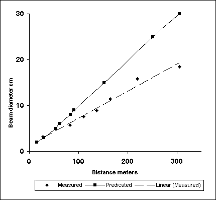
I walked along the measuring line and used a pad of paper to measure the diameter of the beam at distances between 90ft (27 meters) and 720ft (219 meters). An additional diameter measurement was taken on 1/25/2005 at 1000ft (304 meters). The actual beam diameters and the predicted beam diameters, based on a 1 milliradian dispersion, are shown graphically in the following figure:

Figure 20 - Measured and predicated dispersion of a green laser pointer
The actual beam dispersion was significantly less than the 1 milliradian divergence assumed in the FAA study on the biological effects of lasers. The Leading Light Technology, Inc. pointer probably had a higher energy density at a given distance.
At 1000ft (352 meters), I looked down the axis of the beam with the naked-eye for up to thirty seconds with minor glare discomfort.
At increasingly large distances, it becomes more difficult to align the pointer's beam parallel to the roadway. Several attempts were needed to align the beam so that I could view it along its optical axis at a distance of 1300ft (396 meters). 1300ft (396 meters) was a limit beyond which I was unable to align the beam parallel to the roadway. At that distance, even the smallest change in the fine focuser would move the beam several feet.
While at 1300ft (396 meters), a car with high beams on drove next to the pointer positioned on the road's shoulder. I was viewing the pointer's laser beam on-axis. The high beam headlights and an on-axis presentation pointer had a similar relative brightness.
At 1300ft (396 meters), the laser beam's glare does not totally overwhelm the viewer's peripheral vision. With the naked-eye for an indefinite period, I could comfortably look down the axis of the beam without any glare discomfort. The beam creates a glare zone about 20 degrees in diameter. At 1300ft (396 meters), there was a significant attenuation of the beam between 1000ft and 1300ft.
On January 25 and near a full moon, a helper and I went to the Kamas highway site. The site was measured was existing highway deer crossing signs marked "500 feet" and "1000 feet" and a car odometer. The photographs shown and discussed here were taken.
Progressive film exposures were made at 500ft (152 meters) and 1000ft (304 meters). Stepping down the ASA exposure setting from 1600, to 1200 and 1000 changed the exposure length. A final manual "B"-setting one-second exposure was made. One exposure was stepped down to 800 ASA. The best exposures were selected and presented here.
As I walked out to the 500ft (152 meter) sign, I tried at various distances to turn-around and look into the laser beam. I had a reflex instinct to look away from the on-axis beam at distances out to 200ft.
My helper was an intermediate lunar observer. He has little difficulty manually tracking lunar mountains at 200x using an alt-azimuth mounted scope. At 1000ft, he had substantially difficulty aiming the laser beam at me in the near full moon darkness using the tripod mounted binocular and laser. This was because I was not illuminated and the laser beam had no reflection against the backdrop of the night-sky. The reflective deer-crossing highway signs and 3 foot high roadway reflective markers gave reference points that allowed gross aiming of laser beam. Even so, he was unable to intentionally align the laser beam's optical axis with the optical axis of my eyes. I had to position myself in the laser beam to experience its glare.
Although my helper was unable to intentionally align the beam with the optical axis of my eyes, when he randomly jostling the binocular mount, he caused inadvertent glare strikes. I did experience minor disorienting glare during these random "flashes" that lasted a fraction of a second.
Later on the 25th at the Little Mountain/Mt. Dell Reservoir site, we used the mounted binocular-laser and hand-held 10x50mm binocular and hand-held laser to sight along Lines "B" and "C". Where the ground provided a reflective surface at 1000 and 1600 meters, a terminal disk of the laser beam could be seen with binoculars. The reflected disk was not visible with the naked-eye at those distances. The reflected disk of the beam allowed eye-hand coordination and the beam could easily be targeted at those distances using a mounted or hand-held pointer. The terminal disk could not be seen with binoculars when aimed along sight Line "C" at a land feature 3 kilometers distant. There were no convenient land surfaces at distances between 1.6 kilometers and 3 kilometers off of which the beam could be tested.
We attempted to replicate the results of the 1/23/2005 session and to extend the baseline of the observations past 1300 feet (396 meters) along Line "A" and Points "F" and "A". Brightness effects observed between 1000ft (304 meters) and 1300ft (396 meters) were the same as on 1/25/2005, but we were unable to successfully target the laser for a stationary observation along Line "A" at distances beyond 1500ft (457 meters) due to an uneven grade on the road surface.
K. Fisher fisherka@csolutions.net (Org. 10-27-2005; Rev. 11-1-2005)


