3d Milky Way Schematic - VRML World Navigation Tips
Go to: Project homepage Catalogue 3D World (requires Cortona VRML player)
VRML browsers have a standard set of viewer buttons including: Fly, Study, Plan, Pan, Turn, Roll, View and Fit. See the help documentation for the VRML browser you use for an explanation of these common basic features.
Initial viewpoint; Study Mode with world fit
|
The initial viewpoint of the Milky Way Galaxy 3D renderings is hovering above the z-axis and the Sun with a 2 kiloparsec radius circular grid displayed. The grid and 3D world are plotted in the galactic coordinate system. Orion is at the top of the screen and Sagittarius is at the bottom. Cygnus is on the right and Vela on the left.
|
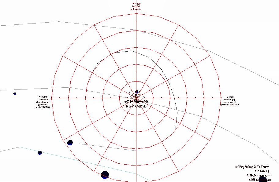
Figure 45 - Initial viewpoint
|
|
The center of rotation of the Milky Way 3D renderings is the center of Milky Way galaxy - 8.5 kiloparsecs distant. From the initial viewpoint, to see the entire Milky Way, press the "Fit" button. In this position, the Milky Way can be rotated in the x-y plane using the "Study" and "Roll" action. Movement is accomplished in a VRML world by a two-step process. First the viewing and movement modes are set with browser buttons. Then click & dragging in the virtual world with the mouse starts the chosen mode of movement. Although difficult to describe with written language, movement is easily learned and because intuitive after a few minutes of practice.
|
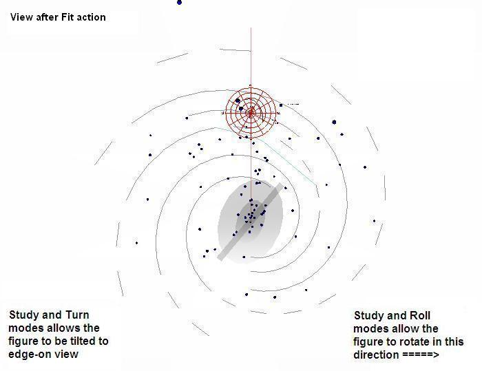
Figure 46 - Z-plane - Milky Way after Fit action
|
|
Using the built-in VRML Study plus Turn modes, rotate the Milky Way 90 degrees to an "edge on" view. You are looking at the Milky Way as if you are inside the Milky Way galactic plane. Now the 3d Milky Way rendering can then be rotated using Study and Turn modes.
|
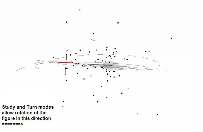
Figure 47 - Milky Way edge-on after Study and Rotate action
|
Preprogrammed viewpoints within 2 kiloparsecs of the Sun
|
Because the center of the 3D rendering is the Milky Way galactic center, a set of preprogrammed viewpoints around the outside of the 2kpc radius grid is provided at 45 degree intervals. These viewpoint intervals correspond to galactic longitude.
|
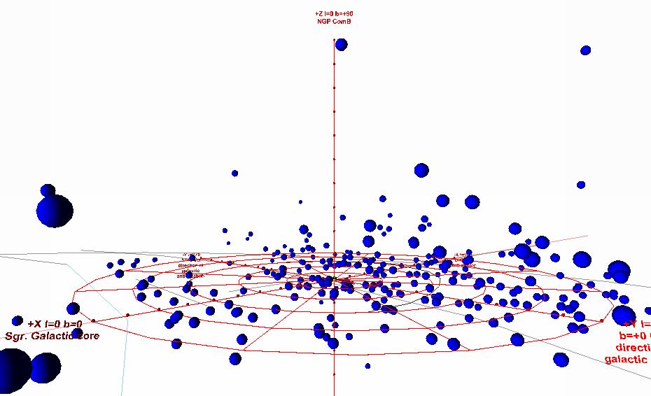
Figure 48 - 45 deg viewpoint around the 2 kpc grid
|
|
The viewpoints are activated using the VRML browser's View menu button. Once at the first viewpoint (at 5 degs latitude above
0 degs galactic longitude) is activated, pressing the {PGDWN} key will cycle through the viewpoints.
|
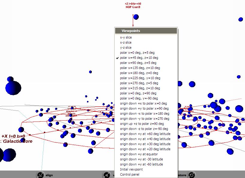
Figure 49 - Viewpoint menu activated
|
|
An alternative to using the 2 kiloparsec preprogrammed viewpoints is to use the Control Panel, described below, to turn the "Galactic Arms" schematic to "off." This will recenter the 3D world near Sol and allow the objects in the 2 kiloparsec grid to be examined using the normal Study and Turn modes. |
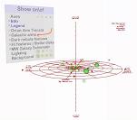
Figure 50 - Study mode with Galactic Arms hidden
|
Fly & Plan and Pan Mode within 2 kiloparsecs of the Sun
|
At times you may wish to Fly and Plan modes to make a virtual flight through the 3D rendering in order to view structural relationships, such as those seen above.
|
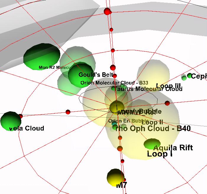
Figure 7 (Repeated) - Structures within 1.5kpc
|
|
The best route to fly from the initial viewpoint above the z-axis is route "A" shown in the following figure - slightly to one-side of the z-axis. To fly to an object inside the 2 kiloparsec grid, the best strategy is to pre-position your virtual avatar using the viewpoint closest to or on the side of the grid directly opposite from the object. Then virtually "fly" forward. See route "B" in the following figure. For example, to virtually fly to the vicinity of the Aquila dark cloud, choose the 45 degree longitude viewpoint and then use Fly and Plan modes to move forward. Fly and Pan mode is used to fly "up" and "down" in the vertical z-plane.
|
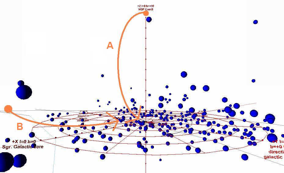
Figure 51 - Fly routes illustrated
|
Object size and object information on rollover
|
Objects are not plotted to size - the objects in the VRML world are positional markers. All of the object points are not plotted at the same size - they are plotted to the size most convenient for viewing in a specific context. For example, tri-axial object locations are plotted as 30 parsecs spheres in near the 2 kiloparsec grid. Globular clusters, which are usually viewed in the larger 30 kpc "Galactic Halo" view, are plotted as 60 parsec spheres. This is best seen in the homepage logo. The galactic halo globulars are plotted on a larger scale than the objects in the arms, because the globulars are normally viewed from a greater virtual distance.
The line extending from the center of the Milky Way galaxy to Sol shown in Figure 51 is the fundamental line of the galactic coordinate system.
|
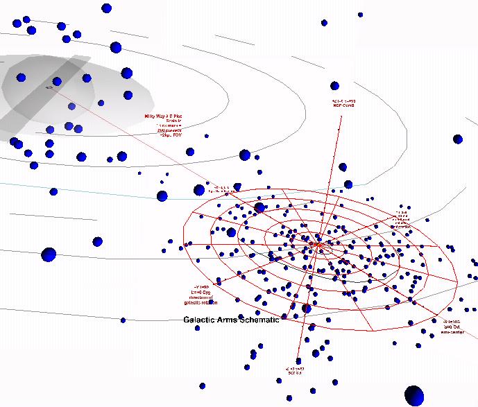
Figure 52 - Homepage logo
|
|
In the 40Mpc Virgo Supercluster view, objects are plotted as 400 parsec spheres - for better visibility, as shown in Figure 53.
|
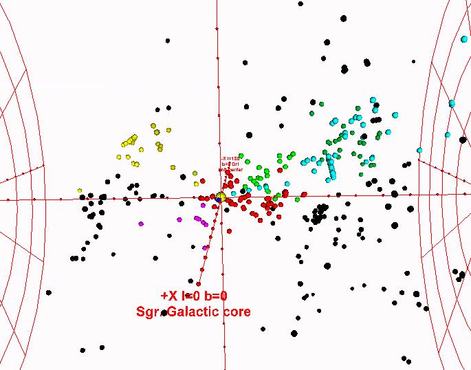
Figure 53 - Virgo Supercluster to 40Mpc
|
|
In some 3D renderings - the structure enhanced views discussed below - objects are rendered according to their diameters, as illustrated in Figure 7. See discussion below.
|

Figure 7 (repeated) - Structures within 1.5 kpc
|
Using the mouse to rollover an object activates object information in the status bar. Information provided includes:
- Catalogue Name - typically the NGC number;
- Object type;
- G2000 coordinates;
- J2000 coordinates; and,
- Solar distance in kiloparsecs.
|
|
External content link to Centre de Données astronomiques de Strasbourg - Simbad
|
In each world, Sol is shown as an off-color, oversize sphere at the grid center. Clicking either Sol or on the Milky Way Galactic Bulge activates a courtesy link to external content: the Simbad database at the Centre de Données astronomiques de Strasbourg - or at the Harvard Smithsonian mirror of the CDS site. Using object rollover, an object's name can be noted down. Then activate the courtesy link to the Simbad database. Type in the object's name in the Simbad search box. The Simbad database can be used to research data and journal articles about that object.
|
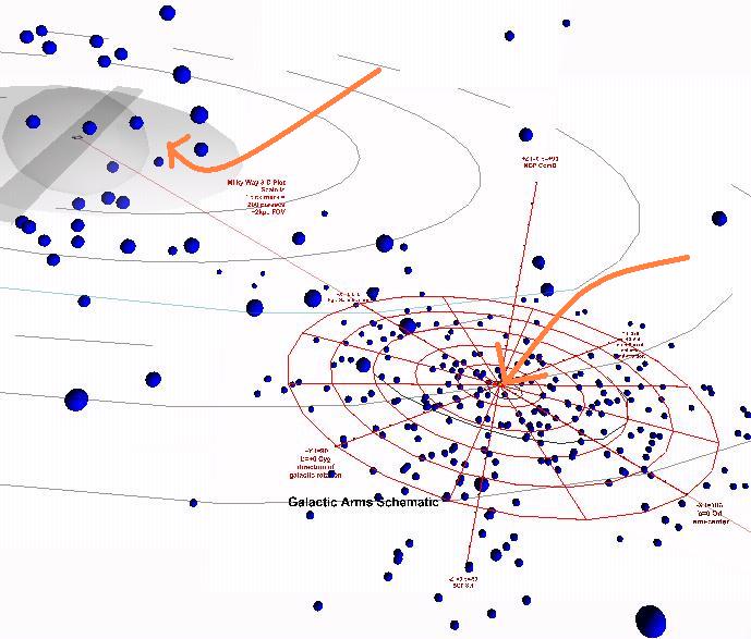
Figure 54 - Hotspots to courtesy external content links
|
|
In some 3D renderings - the structure enhanced views discussed below - the hotspots link to a supplemental information page concerning views of the Milky Way Galaxy seen at various wavelengths of light across the light spectrum.
|
|
Supplemental "raw" or emissive data point renderings
|
One of the viewpoints activates a "Control Panel" or 3-D menu display. In the 3d renderings, the Control Panel virtually hovers about 4 virtual kpc towards the Milky Way galactic bulge.
|
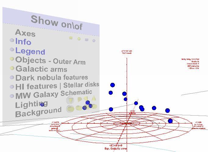
Figure 56 - Control panel
|
|
Buttons on the Control Panel control the display or hiding of features. Features are divided into three main groups:
- Coordinate grid displays;
- Objects and structural features;
- Lighting; and,
- Background.
|

Figure 57 - Control panel option groups
|
Structural views that can be activated with the Control Panel
|
General Structures: Some of the feature options activate views with enhanced schematic details of the Milky Way galaxy within 2 kiloparsecs of the Sun and the HI cloud that surrounds and is an extension of the Milky Way galaxy. Figure 7 illustrates schematic display of molecular dark clouds and HI loops. Enhanced schematic views include various associations, structures and/or classes of objects, such as:
Journal articles supporting the existence and plotting of these schematic details can be found in the Milky Way Structure Reader.
|

Figure 7(repeated) - Structures within 1.5kpc
|
|
Milky Way Galaxy Schematic: The Control Panel option for the "MK Galaxy Schematic" activates a diagram of the basic features of the visible Milky Way (after Dame (1987)) as commonly seen in the galactic plane of the night celestial sphere, i.e. - the "Milky Way." This semi-transparent diagram is wrapped around the 2 kiloparsec grid.
The intent of the wrap-around diagram is to allow beginners to "fly" through the diagram towards the Sun near their Milky Way structure of interest. The triaxial position of the corresponding object is plotted inside. The molecular clouds that we see as the Aquila, Vela and Cygnus Rifts are good examples.
|
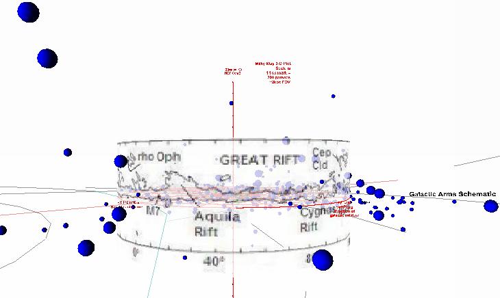
Figure 58 - Wrap-around Milky Way diagram
|
|
|
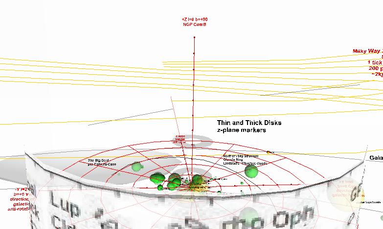
Figure 59 - Looking over the top of the wrap-around diagram at the structures within
|
|
Dark Clouds: One structural schematic renders molecular clouds in Lynds-Barnard catalogues with known distances, principally drawn from Hilton (1995), Dame (1987) (Table 2) and Perrot (2003) (Table A.1 and A.2).
|

Figure 60 - Dark molecular clouds
|
There are seven principal molecular cloud complexes within 1 kiloparsec. Pohl (2003). These complexes, along with the Great Northern Sky structure (Schlosser (1984)), dominant the northern hemisphere view of the night-sky galactic plane and are well-known to amateurs. The enhanced structural view, activated from the Control Panel, labels most of these complexes along with major rifts in Aquila, Vela and Cygnus drawn from Dame (1987) (Table 2):
Table 15 - Molecular Cloud Complexes
| Cloud Complex
|
Gal. longitude (degs)
|
Distance (pc)
|
| Ophiuchus
|
355
|
125
|
| Cassiopeia
|
131
|
350
|
| Cepheus
|
110
|
300
|
| Perseus
|
158
|
350
|
| Taurus
|
165
|
140
|
| Orion
|
208
|
500
|
| Monoceros
|
215
|
830
|
| After Table 1 in Pohl (2003)
|
|
|
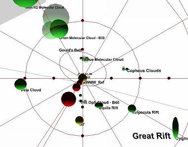
Figure 61 - Molecular complexes and major rifts
|
|
HI Warped Disk: Another structural schematic involves rendering the galactic warp of the plane of the Milky Way using the half-height of the HI gas (non-optical) gas disk after Henderson (1982) between the solar circle and 17 kpc and Binney (1998)'s fitted curve plot between 16 kpc and 30 kpc. (Binney 1998 at p. 566).
|
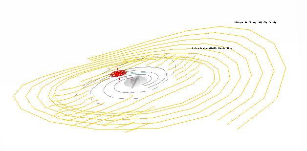
Figure 62 - HI galactic warp
|
|
Galactic group position markers: In the 10Mpc Virgo local cluster and 40 Mpc Virgo supercluster views, the Control Panel activates a series of galaxy group position markers after Giuricin (2000), limited to those galaxy groups with common names. Galaxy group nomenclature, in 2005, is in a state of flux due to an increase in journal publications in this subject area between 1998 and 2005. Detailed plotting of group identifications was deferred for this reason. These markers convey position only; their size is set arbitrarily to 1500 kiloparsec.
|

Figure 63 - Galaxy group markers
|
Microsoft Internet Explorer Active-X security warnings
If this site is accessed over the web, Microsoft Internet Explorer may give Active-X Control security warnings in response to invoking the Parallelgraphics, Inc. Cortona VRML player. Those security prompts can be minimized by accepted the Cortona VRML Player as a trusted Active X control or by making the internet site you access a "trusted site." To make this site a "trusted site:"
- Copy the address of the site from the Microsoft Internet Explorer address bar above;
- Click Tools | Internet Options | Security;
- Click "Trusted Sites";
- Paste the web address into the "Add this Web site to the zone" box; and,
- Press "Okay".
If you have made a local copy of this site on your computer, Microsoft Internet Explorer will give Active-X Control security warnings when the Parallelgraphics, Inc. Cortona VRML player is invoked. There appears to be no way to disable these warnings.
Prepared by: K. Fisher 3/2006 fisherka@csolutions.net


