Portable video meteor camera design 160° TFOV 2.0 TLM Cost 230 USD

fisherka@csolutions.net Org. 1/1/2009

Go to: Description with pictures Parts list Construction instructions Unresolved recording problem

Summary


Figure 1 - Portable meteor cam


Figure 2 - Portable meteor cam deployed in mailbox

This note concerns a design for a portable weather-resistant meteor recording video camera (12" by 3.5", weight approx. 3 lbs) based on a Sony ExView HAD camera board. A portable weatherproof design is presented that has a 160° true-field-of-view (TFOV), a telescopic limiting magnitude (TLM) of 2 magnitudes and a construction cost around 230 USD (2009). This design can be attached to a dovetail bar and a tracking telescope mount. Or this design simply can be stuck in the ground using an incorporated bayonet at a remote observing site.

Current practice for amateur meteor video recording cameras is exemplified by two permanent installation designs. The first is Chris Peterson's Cloudbait Observatory allsky 180° TFOV camera design that can reach a TLM of 0 to 1 magnitudes. The second are modified security cameras with a 68° TFOV that reach a 3 to 4 TLM. The Croatian Meteor Network (CMN) uses these cameras for triangulated video meteor observing. Both designs are based on a Sony ExView HAD chip that can image 0.00001 Lux. The Croatian Meteor Network uses an security camera and inverted housing (Supercircuits CD42IRHR) that in 2009 retails for about 270 USD. Their design's 3 to 4 magnitude TLM is a result of the lens's reduced angular field-of-view. (A lower angular TFOV means a high radiance reaches each camera pixel.) Peterson uses an indoor bullet style security camera (Supercircuits PC164CEX-2) (140 USD in 2009) with a custom built weather housing. A third system based on an image intensifier with a 60° TFOV that reaches a 6.0 TLM is described by the International Meteor Organization.

The design presented here was intended to determine if a weatherized meteor recording camera could be constructed for significantly less than the 270 USD price point achieved by the Croatian Meteor Network by using an inexpensive weatherized landscape spotlight for the housing. At approximately 200-230 USD in construction costs, a significant price savings was not achieved with the design presented here over the CMN design. Diligent web searching can uncover waterproofed security camera designs comparable to the Supercircuits CD42IRHR for 230 USD (2009). Chris Peterson does not stte a cost estimate for his design. I concluded it also was in the range of $200 USD (140 USD for the PC164; 40 USD for the 1.68 mm lens; 27 USD for the acrylic dome).

But the exploration of an alternative design resulted in the adopted version presented here that provides other benefits. It is more suitable to those observers who cannot mount permanent meteor cameras (i.e. - renters vs. homeowners), those who desire a portable field design or a design that can be attached to a tracking telescope mount.

Description of the adopted design

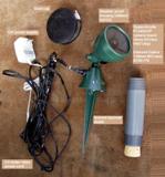
The design presented here is based on a Sony ExView HAD camera board - Supercircuits PC402UXP (119 USD in 2009), an Edmund Optics 1.68mm fl M12 lens with a 160° TFOV (38 USD in 2009) that reaches a 2.0 TLM, and a weatherproof Utilitech landscape spotlight housing. The design is illustrated in Figures 3 through 8:


Figure 3 - Components

Figure 4 - Detail of camera head and lens

Figure 5 - Power and video connections

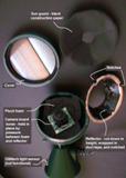
Figure 6 - Camera head disassembled

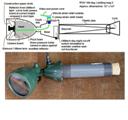
Figure 7 - Schematic - camera housing

Figure 8 - Schematic - 12 foot extension cord

This design is intended to be used with a USB port enabled laptop that uses a separate S-Video capture device, like a Pinnacle Dazzle Video Creator Plus S-Video capture bus ($90 USD in 2009, Best Buy). This author uses a discontinued Belkin S-Video-to-USB capture device. The camera controls on the Belkin video driver includes a gain control. This control (that operates on the video capture card and not the camera chip) provides limited ability to increase the TLM of the captured image.

Results

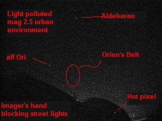
A test image of the constellation Orion in a magnitude 2.0-3.0 light polluted urban environment shows that this design can reach a TLM of 2.0 (the three stars in Orion's Belt). The camera has yet to be tested on a meteor shower.


Figure 9 - Test image on Orion at horizon (labeled)

Design considerations and objectives

My main design criteria was to have a meteor cam that was weather proof and could be temporarily set outside on peak shower nights. I currently have a meteor camera setup based on an astronomy camera, but the camera is too expensive to leave outside at night where it might be stolen. An inexpensive camera that would not present a serious economic theft loss was desireable. The Cloudbait and CMN designs are really for locations where the camera can be mounted permanently outside without fear of theft loss, e.g. - they are homeowner or property owner camera designs.

Since the Sony ExView Super HAD chip appeared to be the generally accepted imaging device, design focus was placed on an inexpensive weatherproof housing for the camera - whether the chip is on the Supercircuits PC402UXP camera board or encased in the Supercircuits PC164CEX-2 bullet camera.

Following considerable web forum discussions, I concluded that defeating automatic gain control and/or the automatic brightness control features of the camera board by building specialized circuits was not necessary.

Security cameras like the Supercircuits CD42IRHR is that they are really designed to be installed under the weatherprotected eaves of buildings with the acrlyic dome housing pointing to towards the ground. Such cameras are not by design intended to be installed exposed directly to the weather with the acrlyic dome housing pointing to the zenith.

After touring a security system showroom and a home repair center, I settled on the Utilitech No. 042122 75W landscape spotlight (20 USD in 2009) for the weatherproof housing. The Utilitech 75W landscape spotlight is a 120V United States household current appliance that is designed to be placed in your yard and be subjected to landscape watering, summer rain and snow without shorting out. The spotlight is UL approved. Utilitech 75W landscape spotlight is designed to be installed in direct exposure to severe weather and remain waterproof.

It was felt that the Utilitech 75W landscape spotlight would be sufficiently weatherproof since it is UL approved not to shock homeowners with lethal household current after prolonged exposed outdoor use. Disassembly of the spotlight supported that assumption. The spotlight contained double rubber seals at three of five exterior joints and substantial single rubber seals at the baseplate and power cord penetration.

The final design of the device also allows for attachment to a dovetail bar and, thus, supports radiant imaging with using a tracking telescope mount.

Unresolved design problems

Strain relief at the power and video cable penetration does not perform sufficiently well.

The Sony ExView HAD camera board radiates a substantial amount of heat. It was not felt that supplemental heating would be needed to prevent the glass cover lens from dewing or frosting over during autumn, winter or spring operation. During summer nights, it may be that the weather proof housing is too sealed and may result in the camera exceeding its operating temperature. Possible modifications include loosening the glass cover during summer or drilling a small hole in the camera housing in order to allow heat to escape during summer. In winter, this hole can be plugged with a rubber stopper.

Access on the camera board of both the automatic gain control and brightness control.

Parts list

Approx. cost: 250 USD exclusive of Section 3.0 parts and capture and editing software.

  1. Camera, lens, dust cap and weather proof housing
  2. Extension cord parts

Construction instructions

Time: Find parts - 3 to 4 hours; Assembly 2 to 3 hours

  1. Base and Head
    1. Remove base plate using Phillips head screwdriver; remove cover; pry out reflector using a flathead screw driver.
    2. Using Phillips head screwdriver in base, remove light sensor. In base, use wirecutters to cut wires for removal of existing Utilitech spot light household current wires.
    3. Retain strain relief C-clamp from base, two 1-1/2" pieces of household current wire and one-half of plastic tubing underneath C-clamp.
    4. In head, use Phillips screw driver to remove light contact points in bottom of head.
    5. From PC402UXP camera board, disconnect existing power and video wire at small adapter plug on bottom of board.
    6. Thread PC402UXP power and video wire assembly through wire hole in base; slip C-clamp and original plastic tubing over PC402UXP power and video wire inside base.
    7. Put dab of bathroom caulk at wire port entry in base for weather seal.
    8. Insert two pieces of household wiring around PC402UXP power and video wire and beneath C-clamp and plastic tubing (to give the wire sufficient volume). Tighten C-clamp for strain relief.
    9. Reinsert non-function light sensor in base to complete weather seal.
    10. Reinstall bottom plate in base.
    11. Wrap two PC402UXP power and video wires (about 10 inches long) with wire ties and tape to make the cable a single unit. (The extension cord will be prepared later).
    12. In the head, prepare pluck-foam piece to insert in head. By experimenting, adjust height of plug foam so the camera lens will rest just below the cover glass.
    13. With serrated kitchen knife, cut plug foam insert from one edge to center.
    14. Using the microscrew driver on the PC402UXP camera board, loosen the retaining screw in side of the threaded lens mount. Remove the existing 90 degree TFOV pinhole lens from the camera board.
    15. Install the 160 degree TFOV 1.68mm Edmund Optics lens. Power up the camera board; adjust the focus; and then lock down the retaining screw on the camera board. (Then lens shown in Figure 4 uses a separate locking ring (seen below the lens in Figure 4), but this was used only because the retaining micro-screw was dropped and lost.)
    16. In head, thread PC402UXP power and video wire assembly up through the middle of the pluck foam; insert pluck foam into head.
    17. Plug PC402UXP power and video wire assembly back into the camera board.
    18. With hacksaw, cut reflector bottom down in height. By experimentation, judge the height of the cut so that the camera will be trapped between the reflector and the plug foam with light pressure.
    19. Cut two notches in the rim of the reflector at 90 degree angles. There are used to install and pry out the reflector during final assembly.
    20. Wrap the bottom half of the cut reflector in duct tape, so it will not damage or short-out the camera board when installed.
    21. To fabricate the sunlight guard from black construction paper, take the Utilitech glass head cover and on scrap cardboard draw a circle around the head. Bisect two chords on the drawn circle to find the center of the circle. Using the pencil compass, measure a circle diameter about 3/8 inch larger than this circle.
    22. Draw this circle on black construction paper. Cut the circle out of the paper. Fold the paper circle into quarters.
    23. Measure the diameter of the camera lens. Cut the center-tip of the folded paper circle so a hole is created at the center of the circle.
    24. Cut the paper circle on a line between the edge and center of the circle.
    25. You now have the parts fabricated shown in Figure 6.
    26. Do final assembly of the head. Install camera and reflector into head. A flat head screwdriver inserted into the reflector notches can be used to lever the reflector so it snaps home within the top of the head. Wrap the sun-light-guard black-construction-paper circle around the base of the camera lens. Use scissors to cut-off any excess paper from the edge of the sun light guard.
    27. Power up your camera and check the final focus of the lens. Lock down the adjusting screw on the side of the camera board threaded lens housing.
    28. Clean the camera lens and the Utilitech glass cover with ph neutral lens cleaner and glass cleaning cloth. Install the Utilitech glass cover. Install the dust cap (sewer pipe cover on the parts list over the head).
    29. Slip the plastic pipe over the bayonet of the Utilitech base. Insert the cork in the bottom of the pipe. Press on the entire unit on a firm surface with the cork down. This will seat the cork into the bottom of the bayonet. The cork and pipe can be removed were it is desireable to field install the all-sky camera at a remote site by forcing the bayonet into the ground.
  2. Extension cord
    1. Install the BNC-female-to-RCA-female adapter into the PC402UXP BNC video terminating connector.
    2. Take the 12 foot single wire RCA speaker extension cord with one female end and one male end. Insert the male end into the BNC-to-RCA terminating connector. Insert the RCA-female-to-male gender changer into the female end of the RCA cord. You now have completed fabricating the video feed extension that terminates as the top connector in Figure 4.
    3. Now begin fabricating the power extension cord shown in Figure 8. Take the 12 foot dual wire RCA speaker extension cord with a total of four male adapters (one male connector on each end the two wires). Split the cord down the middle so you have two single strand cords, each with a set of male RCA connectors on the end.
    4. Using the wire cutters, cut the male RCA connectors off of each end of a single strand of the wire. Using the wire cutters, strip one end of this cable to exposure the two shielded strands of wire within the cable.
    5. Solder the M power male adapter on to one end of this cable. Insert it into the female M power terminating connector of the PC402UXP camera board.
    6. You now have the completed camera assembly with the completed video extension cord and a partially completed power extension cord hanging from one side.
    7. Now bind the two cords together. (We will complete the terminating end of the power extension cord later.) Place the cord ends nearest the camera across your lap. Using the wire cutters, plastic wire ties and black duct tap, secure the two wires together every 6" to 8" inches with the wire ties. Use the wire cutters to clip off any excess leader from the plastic wire ties. Between each set of plastic wire ties, wrap the cords together with duct tape. Continue this process until you reach about 8" from the end of the video and power extension cords. Add two or three extra plastic wire ties at the cord ends for strain relief.
    8. Solder the female M power connnetor on to the end of the power cords. This is the lower cable termination shown in Figure 5.
    9. Plug the 12V DC power supply into the female M power connnetor. See Figure 5.
    10. Split the 12" length of rubber tubing down the middle (on one side). Wrap the tubing around the exposed BNC and RCA connections near the base of the camera and extension cords. Wrap the rubber tubing with black duct tape to complete weather sealing the extension cord assembly.
    11. You now have the completed unit shown in Figures 3 and 1.
  3. Other possible design improvements

Recording

By video meteor recording, we refer to the process by which clips of meteors are extracted from a continuous meteor recordings. The problem of appropriate meteor video capture software for a Windows operating system was not resolved here. The typical solution is Metrec - a DOS-system-based program - that is not well-suited for modern USB-port laptops. Metrec is designed to work with older versions of Windows and desktop systems that have a video capture card with a BNC connector. Metrec, according to the author's homepage requires "a PC with a special frame grabber card [Matrox]. . . . MetRec neither works with TV cards or any frame grabber from a different vendor, nor is it able to read AVI or other video files."

Prepared by K. Fisher fisherka@csolutions.net 12/31/2009